Ok... I'll do my best. In all honesty, I've never taken a pump apart in this detail , so it might take me a bit to get some of the tech terms for the parts right, but I can always go back and edit those as you guys point them out to me. Just let me know so this thread doesn't get 10 miles long. I've taken a little bit of liberty and tried to clarify some points so the translation is not 100% accurate word by word. Here goes:
******************
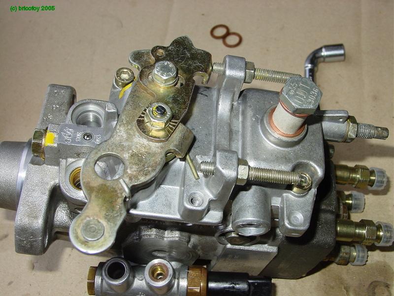
Alright, Folks.... Here’s my Friday night project : prepare a nice working Bosch pump to install on a 205 (Peugeot?).
Since the pump was in unknown condition, it was to be completely taken apart and rebuilt with new gaskets / seals and everything. As it turns out, this was a good move because the inside of it was full of crap..
So…Here’s the starting point, the pump and a packet of seals containing the throttle lever sleeve and the mainshaft seal :

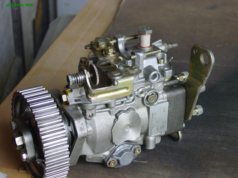
And here's the same thing an hour later..

The Bosch pump looks "crowded" doesn't it?
I didn't take any photos during disassembly, so we'll start from here. If you have any questions about the disassembly, just follow this thread from the bottom up
It goes without saying that once the pump is apart, all the pieces must be rigourously cleaned. In addition, it also greatly helps reassembly to lubricate all parts that adjust, rub or slide together with penetrating oil.
We'll start by reassembling the outlet ports (pressure valves) on the hydraulic head. Here are the different components of the outlet ports: valve, valve spring, adjustment shim, nice new sealing washer and plunger.

The parts reassembled :

and the whole thing :

With that done, let's get on with the "serious" stuff
hoooo, it's completely empty ! You can even see my jeans at the bottom of the hole...

We'll start by reassembling the stator on the transfer pump:
(pay close attention to correctly align the threaded holes with the holes at the bottom of the pump body marked in green)


Next, the rotor and its vanes :

First the rotor :

Next the vanes go in with the help of a long needle nose pliers:


then the rotor cover :

Here it is in place with its screws :

We'll now put the main shaft in place as shown below:

Before putting it back in its place, you have to first put in the governor drive gear along with two new elastic shims/couplers:


Next, add the washer that goes behind it:

and finally the transfer pump drive key in the shaft:

Then you put the whole thing in the body of the pump:

And...here it is in its place :


We'll now put the put the following pieces together: the roller carrier with its actuator pin for timing advance:

Put the actuator pin into the carrier (be sure to put the hole in the pin on the correct side!)

Next, put the assembly in the pump :


...and here's the actuator pin when it's in its appropriate place.

It sticks out into the advance mechanism's bore:


Ok, now all we have to do is assemble the roller carrier so we can put the advance piston in place like so:

Put the assembly back together :

The piston in place :

Pay close attention to the piston's orientation. The machined part of the piston that accepts the spring is installed on the side of the evacuation hole that goes to the transfer pump:

All that's left is to drop the acutator pin in place

and secure it with its pin.


Install the clip on the end of the pin:


Next, we'll put on the transfer assembly cover with a new seal:


Then, on the other side, the spring and the automatic advance mechanism (cold start advance lever / cover for us VW guys?):


Eventually, I removed the electric adavance mechanism since the 205 doesn't have this feature. I put a normal cover in its place.

Next, you install the cross-shaped piece that drives the rest of the pump:


Then install the rollers... They are shown here on their support outside of the pump. Pay close attention to the orientation of the washer which is curved to adapt to the outside shape of the support:


Install the spring that goes in the center :


Next add the camplate which goes on top:


To align this part, the drive pin for the piston (marked in green) must be aligned with the key in the pump's shaft.
It's the cams (humps) of this plate that cause the piston's movement when the rollers pass over them. The piston moves, compresses the fuel and injection occurs. You can modify the advance by turning the roller carrier in relation to the timing advance piston's position underneath.
With this pump, I changed the camplate because this pump's original camplate didn't have the same profile. The one that's in there now comes from a 205 pump.
Now let's go on to the distributor piston:

Next we add the governor assembly:

This piece, directly actuated by the governor, is going to more or less cover the piston's outlet hole (marked in green on the preceeding photo).
During injection, the piston is pushed in, pushed by the camplate. Depending on the position of the governor assembly, the hole becomes more or less blocked by the piston's movement after its stroke. This is how the amount of fuel to be injected is regulated. (when the hole is "free" the pressure is relieved through there and injection stops).
The piston is called the "distributor" because it is driven in rotation and directs the fuel towards each outlet port (pressure valve toward the injector) through each of the different holes on it.
Next, we put the distributor piston back into the hydraulic head:

..and the return springs:


The spacer shim at the end of the piston:


..and it all goes into place in the pump :


We'll now reattach the governor levers and the return springs on them:

The most complicated part of this operation is the correct positioning of the springs:
l


Detail of the how the special triangular head bolts (for which I made a special socket by grinding an old 13mm socket) will fit into the lever assembly:

Installation of the bolts with new aluminum gasket:

The only thing remaining on this step is to put the lever assembly in from the top:

...And no...that doesn't work. We're screwed. Impossible to do it this way. We'll have to disassemble the head and then put the levers in place before all of the rest.
By the way, on the distributor piston, you'll see the outlet orifice (marked in green), the orifice leading to the injectors (red) and the 4 grooves that fill the chamber at the end (green). The piston is hollow to allow flow through to all of that.

The head assembled with all its return springs:

The only thing left here is to put everything back into place then disassemble it one or two more times after the springs fall out in the process...and here you go:


Let's go on now to the reassembly of the centrifugal governor. Here are all the pieces:

First you put together the counterweights:


Then you put them back into the body of the governor:

Next, you replace the governor lever seen below. (notice the calibrated hole that's part of the system that alters the initial fuel injection in function of the load):


After this, you put in the governor shaft in the body of the pump:

These are the washers that go behind the governor's rotor:


the governor itself :


Then install the shaft and tighten it with the help of a hex key and a normal box wrench to hold the shaft in position so it doesn't move while the lock nut is tightened.
The position of this shaft is important because it regulates the system of initial injection by vacuum (?). It's wise therefore, to mark the position of this shaft during pump disassembly.

There you go... Now the pump body is complete. The only things missing are the pump cover and the transfer pressure regulation valve that I could have put on right after this, but didn't...
We'll start by removing the old lever guide sleeve:


Then we put the new sleeve in its place:

Gently push the sleeve home by using a bolt and some large washers:


Next, put in the governor shaft and return spring "capsule":

Detail shot of the attachment of the governor spring assembly on the governor lever: the flat (green) fits into the slot/grove in the lever (red) then gets pulled into place from behind:

And there you go... just have to replace the cover (with a new seal) and screw it into place.
Next, you put the throttle lever back in its place thanks to the markings on the shaft and on the lever (we would have obviously have taken care to mark it's exact position during disassembly):


Now, put the transfer pressure regulation valve back on (with new o-ring seals, of course):


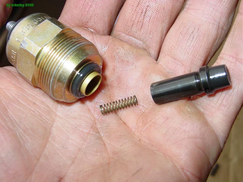
Next, add the electric fuel cutoff solenoid :


And finally, install the seal on the mainshaft (you can do this by using a large socket and the pump's shaft pulley nut to press it into place on the shaft...sorry, no photo,).


And there you go, all done. Nothing left to do but to install it onto the 205!
